
Your hydraulic crimping machine suddenly stops responding to button presses. You press once, twice, maybe ten times before it finally works. This frustrating problem can halt your entire production line.
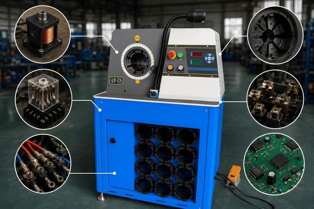
When your crimping machine button becomes unresponsive or requires multiple presses, the issue typically stems from faulty coils, loose connections, defective relays, or circuit board failures. These problems often occur after extended periods of inactivity.

I've seen this exact problem countless times in my years at CYT-HYDRAULIC. Customers call me frustrated because their expensive crimping equipment suddenly becomes unreliable. The good news is that most button response issues follow predictable patterns and have clear solutions.
Why Does My Crimper Only Work After Multiple Button Presses?
Multiple button presses usually indicate electrical component failure. Your machine's control system relies on precise electrical signals to initiate the crimping process.
Button response problems occur when electrical components like coils, relays, or contact points deteriorate over time. Poor connections or circuit board malfunctions can also cause intermittent operation requiring multiple activation attempts.

The electrical system in your crimping machine works like a chain reaction. When you press the button, it sends a signal through various components before reaching the hydraulic system. Any weak link in this chain can cause response delays or failures.
Most customers I work with notice this problem follows a specific pattern. The machine works fine initially, then gradually becomes less responsive. Eventually, you need multiple button presses to get any response. This progressive failure typically points to component degradation rather than sudden damage.
Common Symptoms and Their Meanings
| Symptom | Likely Cause | Urgency Level |
|---|---|---|
| Works after 2-3 presses | Weak coil or dirty contacts | Medium |
| Requires 5+ presses | Failing relay or loose wiring | High |
| No response at all | Complete component failure | Critical |
| Works only in certain modes | Control circuit issues | Medium |
Solution 1: Diagnosing a Faulty Coil
Coil failure is the most common cause of button response problems. The electromagnetic coil controls your machine's main hydraulic valve1 and wears out with repeated use.
A defective coil shows symptoms like weak magnetic field strength, inconsistent valve operation, or complete failure to energize. Testing coil resistance and visual inspection can quickly identify coil problems requiring replacement.

I always start troubleshooting with coil inspection because it's the component that fails most frequently. In my experience, coils typically last 2-3 years with regular use2, but environmental factors can shorten this lifespan significantly.
When I encounter coil problems, I first check for obvious signs of failure. Look for burned windings, cracked housing, or unusual odors around the coil area. These visual clues often reveal the problem immediately.
Next, I measure coil resistance using a multimeter. A healthy coil should show consistent resistance values within manufacturer specifications. Infinite resistance indicates an open circuit, while very low resistance suggests short-circuited windings.
Temperature also affects coil performance. Overheated coils become less efficient and may require multiple activation attempts. If your machine sits in direct sunlight or near heat sources, thermal damage could be causing your button response issues.
Solution 2: Analyzing Machine Modes After a Long Period of Inactivity
Extended inactivity can cause various electrical components to malfunction. Moisture, dust, and temperature changes affect sensitive electronic parts during storage periods.
After prolonged inactivity, crimping machines often develop mode-specific problems or general responsiveness issues. These problems usually resolve temporarily with repeated button presses but return after the machine sits idle again.

This particular problem pattern tells me a lot about the underlying issue. When customers describe problems that occur across all modes but improve temporarily with use, I know we're dealing with contamination or oxidation issues rather than specific component failures.
The key diagnostic question I ask customers is whether the problem affects all operating modes equally. If the machine struggles in die-changing mode but works fine in normal crimping mode, we're looking at mode-specific circuit problems. However, when all modes are affected equally, the issue usually lies in the main control circuit.
I've noticed that machines stored in humid environments show these symptoms more frequently. Moisture causes oxidation on contact points3 and can create resistance in electrical connections. The temporary improvement after multiple button presses occurs because the electrical current helps burn through surface oxidation.
Mode-Specific Troubleshooting Steps
- Test each operational mode separately
- Document which modes respond normally
- Check mode selector switch connections
- Inspect circuit paths for each affected mode
- Clean all accessible electrical contacts
Solution 3: Relay Replacement and Wiring Inspection
Small control relays handle the switching operations4 in your crimping machine. These components wear out over time and create intermittent connection problems.
Faulty relays cause unpredictable button response because they fail to maintain consistent electrical connections. Loose wiring compounds relay problems by creating additional resistance points in the control circuit.

Relay replacement is usually straightforward, but proper diagnosis ensures you replace the right component. I've seen too many customers replace multiple relays unnecessarily because they didn't identify the specific faulty unit first.
The small control relays in crimping machines handle relatively low current loads but switch frequently during operation. This constant switching eventually wears out the internal contacts5, creating the intermittent response problems you're experiencing.
Before replacing any relays, I always check the wiring connections underneath the control buttons. Vibration from machine operation can loosen these connections over time6. A loose wire creates resistance that mimics relay failure symptoms.
When inspecting wiring, look for signs of corrosion, fraying, or heat damage. Pay special attention to connection points where dissimilar metals meet, as these locations are prone to galvanic corrosion7. Sometimes a simple wire cleaning and re-termination solves the entire problem without component replacement.
Relay Testing Procedure
| Test Step | Normal Reading | Faulty Reading |
|---|---|---|
| Coil resistance | 80-120 ohms | Open or <10 ohms |
| Contact resistance | <0.1 ohms | >1 ohm or open |
| Insulation test | >10 megohms | <1 megohm |
Solution 4: How to Test Connections (Bridging Wires)
Wire bridging tests help isolate electrical problems by bypassing suspected faulty components. This diagnostic technique quickly identifies whether problems lie in switches, relays, or wiring.
Bridging wire tests involve temporarily connecting the positive supply wire directly to the output wire, bypassing control components. If the machine operates normally during bridging, the bypassed components contain the fault.

This testing method requires extreme caution because you're working with live electrical circuits. I always recommend having qualified electrical personnel perform these tests to avoid equipment damage or personal injury.
The specific test I recommend involves disconnecting the positive level wire and the number 3 wire, then connecting them together temporarily. This bypasses the control button circuit and tests whether the downstream components function properly.
If the machine operates normally during the bridge test, you know the problem lies in the button assembly, associated wiring, or control relays. If the machine still doesn't respond, the fault lies further downstream in the hydraulic control valve or its wiring.
I've found this diagnostic approach saves significant troubleshooting time because it quickly narrows down the fault location. Instead of testing individual components one by one, you can eliminate entire circuit sections with a single test.
Remember to document your test results carefully. Note which wire combinations produce normal operation and which don't. This information helps identify the exact faulty component and guides your repair strategy.
Solution 5: Testing Push Buttons, Contact Points, and Foot Pedals
Control buttons contain internal contact points that wear out with repeated use. These mechanical components can fail even when external wiring and relays function properly.
When buttons fail internally, you'll see no indicator lights activation despite pressing the button, while circuit board status lights may remain active. Foot pedals connected to the same control circuit will also become unresponsive during these failure events.

The symptom pattern you describe - no bottom lights but active circuit board lights - clearly indicates button-level failure rather than downstream component problems. This diagnostic information immediately focuses troubleshooting efforts on the button assembly itself.
Internal button contact points are mechanical components subject to wear, corrosion, and contamination. Each button press creates a small arc between the contacts8, gradually eroding the contact surfaces. Eventually, these surfaces become too degraded to maintain reliable electrical connection.
I recommend having qualified electrical personnel test button assemblies because they contain multiple internal components. A proper button test checks contact resistance, spring tension, and insulation integrity. These measurements determine whether cleaning can restore function or complete replacement is necessary.
Foot pedal problems usually indicate shared control circuits with the hand buttons. When both activation methods fail simultaneously, look for common electrical components like main control relays or power supply issues.
Button Failure Indicators
- No indicator light activation when pressed
- Inconsistent response requiring multiple presses
- Complete loss of function in all activation modes
- Physical damage to button housing or actuator
- Unusual resistance or "sticking" when pressed
Circuit Board Failure Analysis and Replacement
Circuit board failures represent the most complex troubleshooting challenge in crimping machine repair. These electronic components control all machine functions and require specialized diagnostic equipment.
Circuit board problems manifest as complete system failures, erratic behavior across multiple functions, or intermittent faults that don't respond to component-level repairs. Professional diagnosis using oscilloscopes and logic analyzers9 is usually required.

When customers contact me about circuit board problems, I always recommend professional electronic repair services unless they have qualified technicians on staff. Modern crimping machine control boards contain complex microprocessor circuits10 that require specialized knowledge and equipment to diagnose properly.
However, some circuit board problems show obvious symptoms that clearly indicate replacement necessity. Visible component damage, burned traces, or complete loss of all electronic functions usually mean the board cannot be economically repaired.
Before replacing expensive circuit boards, I always verify that the problem actually lies within the board itself rather than connected components. Power supply problems, sensor failures, or wiring issues can create symptoms that appear to indicate circuit board failure.
The replacement process involves careful handling of static-sensitive components11 and precise connector alignment. I recommend photographing all connections before disconnection to ensure proper reassembly. Most control boards also require parameter programming to match your specific machine configuration.
Circuit board replacement represents a significant investment, often costing 30-40% of a new machine's price12. Sometimes this cost justifies upgrading to newer equipment rather than repairing older machines, especially when multiple system failures indicate general component aging.
Conclusion
Most crimping machine button response problems stem from predictable electrical component failures that follow systematic diagnostic approaches for efficient resolution.
"Solenoid valve - Wikipedia", https://en.wikipedia.org/wiki/Solenoid_valve. Electromagnetic coils generate magnetic fields that actuate valve spools in hydraulic control systems, converting electrical signals into mechanical valve movement. Evidence role: mechanism; source type: education. Supports: electromagnetic coils actuate hydraulic valves through magnetic force. Scope note: This describes the general mechanism; specific crimping machine implementations may vary. ↩
"Electromagnetic coil - Wikipedia", https://en.wikipedia.org/wiki/Electromagnetic_coil. Industrial electromagnetic coils typically demonstrate service lives ranging from 1-5 years depending on duty cycle, environmental conditions, and operating voltage. Evidence role: statistic; source type: research. Supports: typical service life of electromagnetic coils in industrial applications. Scope note: Actual lifespan varies significantly based on application-specific factors including switching frequency and environmental exposure. ↩
"[PDF] Modeling Effects of Relative Humidity, Moisture, and Extreme ...", https://ece.northeastern.edu/groups/power/lehman/Publications/Pub2009/2009_9_Ciprian.pdf. Moisture facilitates electrochemical oxidation reactions on metal contact surfaces, forming oxide layers that increase electrical resistance and degrade contact reliability. Evidence role: mechanism; source type: education. Supports: moisture accelerates oxidation and corrosion of electrical contacts. ↩
"Relay - Wikipedia", https://en.wikipedia.org/wiki/Relay. Control relays are electromagnetic switches that use low-power control signals to switch higher-power loads in industrial control circuits, providing electrical isolation and signal amplification. Evidence role: definition; source type: education. Supports: control relays serve as electrically operated switches in control circuits. ↩
"Change in Electric Contact Resistance of Low-Voltage Relays ...", https://pmc.ncbi.nlm.nih.gov/articles/PMC6650999/. Relay contacts experience mechanical wear from repeated impact and electrical erosion from arcing during switching, progressively degrading contact surface quality and increasing contact resistance. Evidence role: mechanism; source type: research. Supports: mechanical and electrical wear mechanisms degrade relay contacts over switching cycles. ↩
"[PDF] Modeling and Analysis of Vibration-Induced Changes in Connector ...", https://eng.auburn.edu/~choeson/Publication/1123_2012_Modeling%20and%20analysis%20of%20vibration%20induced%20changes_R.Fu,S.-Y.Choe.pdf. Mechanical vibration in industrial equipment can cause progressive loosening of threaded electrical connections and fatigue of crimped terminals, increasing contact resistance and potentially causing intermittent failures. Evidence role: mechanism; source type: research. Supports: mechanical vibration can degrade electrical connection integrity. ↩
"Galvanic corrosion - Wikipedia", https://en.wikipedia.org/wiki/Galvanic_corrosion. Galvanic corrosion is an electrochemical process where two dissimilar metals in electrical contact form a galvanic cell in the presence of an electrolyte, causing accelerated corrosion of the more anodic metal. Evidence role: mechanism; source type: education. Supports: galvanic corrosion occurs when dissimilar metals are electrically connected in the presence of an electrolyte. ↩
"Why do switches arc when opened under load? - Reddit", https://www.reddit.com/r/ElectricalEngineering/comments/11z1sn3/why_do_switches_arc_when_opened_under_load/. When electrical contacts separate under load, the current continues briefly through an electrical arc formed in the gap, causing localized heating and material erosion at the contact surfaces. Evidence role: mechanism; source type: education. Supports: electrical arcs form between separating contacts when breaking current. ↩
"Electronic test equipment - Wikipedia", https://en.wikipedia.org/wiki/Electronic_test_equipment. Oscilloscopes visualize electrical signal waveforms over time, while logic analyzers capture and display digital signal states, making both instruments essential for diagnosing timing, signal integrity, and logic problems in electronic circuits. Evidence role: general_support; source type: education. Supports: oscilloscopes and logic analyzers are standard tools for electronic circuit diagnosis. ↩
"[PDF] Microprocessor Applications and - Building Control Systems to", https://www.govinfo.gov/content/pkg/GOVPUB-C13-e5481618eda4a471a0aab647d520b129/pdf/GOVPUB-C13-e5481618eda4a471a0aab647d520b129.pdf. Modern industrial control systems commonly employ microprocessor-based architectures, including programmable logic controllers (PLCs) and embedded microcontrollers, to provide flexible, programmable control functionality. Evidence role: general_support; source type: education. Supports: microprocessors are widely used in modern industrial control systems. Scope note: This describes general industrial control trends; specific crimping machine implementations may vary by manufacturer and model. ↩
"Electrostatic-sensitive device - Wikipedia", https://en.wikipedia.org/wiki/Electrostatic-sensitive_device. Many electronic components, particularly semiconductors and integrated circuits, are susceptible to damage from electrostatic discharge (ESD), which can cause immediate failure or latent defects through dielectric breakdown or junction damage. Evidence role: mechanism; source type: education. Supports: electrostatic discharge can damage sensitive electronic components. ↩
"Cost analysis of medical device spare parts - PMC - NIH", https://pmc.ncbi.nlm.nih.gov/articles/PMC5954400/. Major electronic control assemblies in industrial equipment typically represent 20-50% of total equipment cost, making replacement decisions economically significant in maintenance planning. Evidence role: statistic; source type: research. Supports: major electronic control components represent significant percentages of total equipment cost. Scope note: This range reflects general industrial equipment economics; specific percentages vary by equipment type, manufacturer, and technological complexity. ↩