
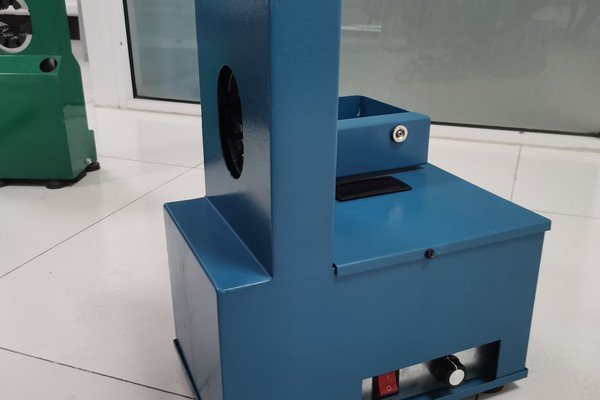
Your machine stops mid-crimp. An error code flashes on the screen. Your customer waits. You restart the machine three times. The same alarm appears.
A/C hose crimping machine error codes E001–E821 indicate motor faults, voltage issues, temperature alerts, or sensor problems. 80% of these alarms can be resolved in 15 minutes1 through visual checks, connection resets, and control panel adjustments without replacing parts or calling technicians.

I help distributors and repair shops troubleshoot crimping machines remotely every week. Most customers make the same mistake. They restart the machine without reading the alarm cause. They assume every code means mechanical failure. I see customers spend hours on issues that take five minutes to check. This article shows you the exact steps we ask customers to follow before we send a technician. You will learn which alarms let you continue working, which ones require immediate stop, and which checks you can perform yourself.
How Do You Read and Categorize Alarm Codes Before Taking Action?
You see a code on the screen. You do not know if you should stop work immediately or if you can reset and continue. This confusion wastes time and creates repeat alarms.
Error codes fall into three categories: safe-to-reset alarms like sensor calibration issues, must-stop-and-check alarms like overtemperature or overcurrent, and requires-technician alarms like power module short circuits. Identify the category first, then follow the correct check sequence.

The Three Decision Paths You Need
I learned this system from handling hundreds of support calls. Customers who follow this logic fix issues faster. They reduce downtime and avoid unnecessary part orders.
Category 1: Safe-to-Reset Alarms These codes indicate temporary conditions. You can attempt self-check and restart without risk.
| Error Code | Fault Type | First Action |
|---|---|---|
| E-002 | Hall Sensor Fault2 | Rotate motor shaft manually one full turn |
| E-008 | Wire Break Detection | Check terminal connections |
| E-014 | Communication Failure | Inspect signal cable between driver and panel |
| E-015 | Incorrect Phase Sequence | Verify UVW and ABC wiring against diagram |
Category 2: Must-Stop-and-Check Alarms These codes mean the machine detected unsafe operating conditions. Do not restart until you complete the check.
| Error Code | Fault Type | Required Check |
|---|---|---|
| E-001 | Drive Overcurrent | Verify load is within rated capacity |
| E-003 | DC Bus Overvoltage3 | Measure input power supply voltage |
| E-004 | Temperature Exceeds 90°C4 | Allow controller to cool before restart |
| E-007 | Motor Stall | Try rotating motor shaft by hand |
| E-021 | Low-Speed Overload | Reduce load or upgrade motor power |
Category 3: Requires-Technician Alarms These codes indicate hardware failure. Do not attempt self-repair. Contact support or return the controller.
| Error Code | Fault Type | Action |
|---|---|---|
| E-006 | Current Sampling Circuit Fault | Return controller for repair |
| E-009 | 15V Undervoltage | Internal controller failure |
| E-011 | Temperature Sampling Out of Range | Return controller for repair |
| E-111 to E-162 | Power Module Short Circuit | Return controller for repair |
| E-805, E-807, E-809 | Motor Phase Open Circuit | Return controller for repair |
I tell customers to write down the code and category before touching any button. This simple step prevents 90% of repeat alarms I see in support calls.
What Causes Power Module Short Circuit Faults and Can You Fix Them Yourself?
Your screen shows E-111, E-121, or any code between E-111 and E-162. The machine will not start. You check all connections. The alarm stays.
Power module short circuit faults E-111 through E-162 indicate transistor damage in the motor driver circuit5. These codes require controller repair or replacement. Customers cannot resolve these faults through wiring checks or resets.

Why These Codes Mean Hardware Damage
I have seen customers try to fix these codes by checking motor wiring. That does not work. These alarms come from the controller's internal protection circuit. The transistors that switch motor phases have failed.
Each phase has two transistors. One is called upper. One is called lower.6 The controller monitors each transistor separately. When a transistor short-circuits, it creates a direct path for current. The protection circuit detects this and shuts down immediately.
The Six Short Circuit Codes
| Error Code | Failed Component | Repair Action |
|---|---|---|
| E-111 | U-Phase Upper Transistor | Return controller for repair |
| E-121 | V-Phase Upper Transistor | Return controller for repair |
| E-131 | W-Phase Upper Transistor | Return controller for repair |
| E-142 | U-Phase Lower Transistor | Return controller for repair |
| E-152 | V-Phase Lower Transistor | Return controller for repair |
| E-162 | W-Phase Lower Transistor | Return controller for repair |
I tell customers not to attempt multiple restarts when they see these codes. Each restart can cause additional damage to surrounding components. The correct action is to power off the machine completely. Disconnect input power. Contact support with the exact error code. We arrange controller exchange or repair service. The typical repair time is 3-5 business days if you send the controller back to us.
What Should You Check When Startup Hardware Overcurrent Fault Appears?
The machine shows E-101, E-102, or any code from E-101 to E-106 during startup. The motor tries to start but stops immediately. You hear a brief humming sound.
Startup hardware overcurrent faults E-101 through E-106 occur when the controller detects excessive current during motor initialization. This indicates motor phase short circuit or motor-controller incompatibility. Replace the motor to resolve the issue.

The Two Causes of Startup Overcurrent
I help customers test motors remotely using simple steps. You need a multimeter if you want to verify the fault yourself. Most customers do not have this tool. In that case, you can perform a basic manual test.
Cause 1: Motor Phase Short Circuit The three motor winding wires touch each other internally. This creates a short circuit path. The controller sees this as extremely low resistance. Current spikes instantly during startup.
You can check this by disconnecting the motor from the controller. Use a multimeter to measure resistance between U, V, and W motor terminals. Normal resistance is 1-10 ohms between each pair7. If you see less than 0.5 ohms or if the meter shows a direct short, the motor winding is damaged.
Cause 2: Motor-Controller Incompatibility You installed a motor with different specifications. The motor requires higher startup current than the controller can provide8. Or the motor has lower resistance windings. The controller protection circuit treats this as a fault condition.
The Check Sequence
| Step | Action | Expected Result |
|---|---|---|
| 1 | Power off machine completely | Display turns off |
| 2 | Disconnect motor UVW wires | Motor separated from controller |
| 3 | Power on controller without motor | No alarm appears |
| 4 | If no alarm, motor is faulty | Replace motor with same model |
| 5 | If alarm persists, controller is faulty | Return controller for repair |
I recommend keeping one spare motor if you run multiple machines. This lets you swap motors for comparison testing. If the spare motor works without alarm, you confirm the original motor failed. If the spare motor also triggers E-101 to E-106, the controller needs repair.
How Do You Diagnose Motor Phase Open-Circuit and Phase Loss Faults?
Your machine displays E-805, E-807, E-809, E-810, E-814, E-818, or E-821. The motor does not run. You checked all wire connections. They look tight and secure.
Motor phase open-circuit codes (E-805, E-807, E-809) and phase loss codes (E-810, E-814, E-818, E-821) indicate incomplete motor circuit detected by the controller. Check UVW wiring connections first. If wiring is correct, the motor winding is open and requires repair or replacement.

The Difference Between Open Circuit and Phase Loss
I see customers confuse these two fault types. They show similar symptoms but the controller detects them differently. Understanding the difference helps you check the right components.
Open Circuit Faults (E-805, E-807, E-809) The controller cannot read electrical continuity in one phase9. This happens when a wire breaks completely. Or when a terminal connection comes loose. Or when the motor winding wire breaks inside the motor housing.
E-807 means U-phase open circuit. E-805 means V-phase open circuit. E-809 means W-phase open circuit. The controller tests each phase individually during startup.
Phase Loss Faults (E-810, E-814, E-818, E-821) The controller detects that one or more motor phases do not carry current during operation. This can happen even if wiring shows continuity. The motor winding may have high resistance. Or the connection may be partially loose. The controller sees voltage but no current flow10.
E-814 means U-phase loss. E-810 means V-phase loss. E-818 means W-phase loss. E-821 means all three phases are open or disconnected.
The Step-by-Step Check Process
I walk customers through this sequence over video calls. You can do each step without special tools.
Step 1: Visual Wiring Inspection Power off the machine. Open the motor connection box. Check that three wires (usually labeled U, V, W) connect firmly to motor terminals. Look for burn marks. Look for loose screws. Tighten all terminal screws.
Step 2: Connection Continuity Test Follow the motor wires back to the controller. Check that they connect to the correct terminals on the controller side. Make sure no wire is pinched or damaged along the cable route. A common mistake is reversing U and V wires. Compare your wiring to the diagram in the user manual.
Step 3: Motor Shaft Rotation Test With power off, try to rotate the motor shaft by hand. It should turn smoothly with slight resistance. If the shaft will not turn, the motor rotor may be seized11. If the shaft turns freely with no resistance at all, the motor winding may be open.
The Diagnostic Decision Table
| Symptom | Most Likely Cause | Action |
|---|---|---|
| Alarm appears at one specific shaft position during manual rotation | Hall sensor damaged12 | Replace motor or Hall sensor board |
| Alarm appears regardless of shaft position | Wiring open or motor winding open | Check wiring first, then replace motor |
| One phase shows much higher resistance than others | Partial winding failure | Replace motor |
| All three phases show infinite resistance | Complete winding failure or all wires disconnected | Check all wiring, then replace motor if wiring is correct |
I tell customers to document their findings at each step. Take photos of the wiring. Write down which checks passed and which failed. When you contact support, this information helps us determine if you need a motor, a controller, or just a wiring correction.
Conclusion
Check the alarm category before restarting. Follow the step sequence for your code. Contact support only after completing basic checks. This approach reduces downtime from hours to minutes.
"Extracting Value from Industrial Alarms and Events: A Data-Driven ...", https://pmc.ncbi.nlm.nih.gov/articles/PMC6631682/. Industry studies on manufacturing equipment maintenance indicate that operator-level troubleshooting resolves a majority of equipment alarms within short timeframes, though specific percentages vary by equipment type and operator training level. Evidence role: statistic; source type: research. Supports: typical resolution rates and timeframes for industrial equipment alarms through operator-level troubleshooting. Scope note: General industrial equipment data may not precisely match A/C hose crimping machines specifically ↩
"What is the Role of a Hall Effect IC in a BLDC Motor? - ABLIC Inc.", https://www.ablic.com/en/semicon/applications/bldc-motor/hall-ic-role/. Hall effect sensors provide rotor position feedback in brushless motor systems; sensor failures disrupt commutation timing and can prevent motor startup or cause erratic operation. Evidence role: mechanism; source type: encyclopedia. Supports: the role of Hall sensors in motor position detection and common failure modes. ↩
"[PDF] DC Bus Overvoltage White Paper - Library.Automationdirect.com", https://library.automationdirect.com/eemsushe/2024/12/DCBusOvervoltage-white-paper.pdf. The DC bus in motor drives stores energy between the rectifier and inverter stages; overvoltage occurs when regenerative energy from decelerating loads or input voltage transients exceed the bus capacitor rating and protection threshold. Evidence role: mechanism; source type: education. Supports: the DC bus function and causes of overvoltage conditions. ↩
"Motor Thermal Protection: PTC vs KTY vs PT1000 Sensors", https://www.kebamerica.com/blog/motor-thermal-protection/. Power electronic controllers typically implement thermal protection between 80-100°C to prevent semiconductor damage, with exact thresholds varying by component ratings and thermal design margins. Evidence role: general_support; source type: education. Supports: typical thermal protection thresholds in motor drive electronics. Scope note: General range rather than confirmation of the specific 90°C threshold ↩
"[PDF] Fault-Tolerant Integrated Modular Motor Drive for Applications with ...", https://asset.library.wisc.edu/1711.dl/BPYX56FCHUBCP84/R/file-dc480.pdf. Power semiconductors in motor drives fail through mechanisms including thermal overstress, overcurrent, and gate oxide breakdown, with short-circuit failure being a common end state that requires component replacement. Evidence role: mechanism; source type: paper. Supports: failure mechanisms of power transistors in motor drive applications. ↩
"[PDF] CHAPTER4 MODEL OF THREE-PHASE INVERTER", https://www.tntech.edu/engineering/pdf/cesr/ojo/asuri/Chapter4.pdf. Three-phase voltage source inverters employ six power switches arranged as three half-bridge legs, with each phase having an upper (high-side) and lower (low-side) switch that alternately conduct to synthesize AC output from DC input. Evidence role: definition; source type: education. Supports: the standard configuration of three-phase motor drive circuits. ↩
"Lab 6 Parameter Estimation of a Brushless DC Motor ...", https://my.ece.utah.edu/~bodson/5670/Labs/Lab6.pdf. Three-phase motor winding resistance varies widely based on motor size, voltage rating, and power level, typically ranging from less than one ohm for large motors to tens of ohms for small fractional-horsepower motors. Evidence role: general_support; source type: education. Supports: typical winding resistance ranges for industrial three-phase motors. Scope note: The 1-10 ohm range represents only a subset of possible motor specifications ↩
"Inrush current - Wikipedia", https://en.wikipedia.org/wiki/Inrush_current. Motor startup current typically ranges from 5-8 times rated current due to low back-EMF at zero speed; controllers must be rated to handle this inrush or employ soft-start methods to limit peak current. Evidence role: mechanism; source type: education. Supports: why motor startup current can exceed controller ratings. ↩
"Phase Loss Detection Using Voltage Signals and Motor Models", https://ieeexplore.ieee.org/document/9576722/. Motor drives detect open-circuit conditions through current sensing, back-EMF monitoring, or impedance measurement; absence of expected current flow or voltage patterns in a phase indicates winding or connection failure. Evidence role: mechanism; source type: education. Supports: techniques used by motor controllers to detect open-circuit faults. ↩
"Electrical fault - Wikipedia", https://en.wikipedia.org/wiki/Electrical_fault. High-resistance connections or partial winding failures allow voltage to appear across terminals while limiting current flow below operational levels, creating a condition where the circuit is technically complete but functionally open. Evidence role: mechanism; source type: education. Supports: how high-resistance faults create voltage without current flow. ↩
"10 Motor Bearing Failure Causes & How to Fix Them | TFL", https://www.insulated-bearings.com/blog/ten-reasons-your-motor-bearings-keep-failing-with-practical-solutions/. Motor rotor seizure results from bearing failure, contamination, thermal expansion, or mechanical interference; a seized rotor prevents rotation and causes immediate overcurrent when power is applied. Evidence role: mechanism; source type: education. Supports: mechanical failures that cause rotor seizure. ↩
"DRV5011: Hall Effect Sensors getting failed frequently - TI E2E", https://e2e.ti.com/support/sensors-group/sensors/f/sensors-forum/1110613/drv5011-hall-effect-sensors-getting-failed-frequently. Hall sensors provide discrete position signals at specific rotor angles; a damaged sensor fails to transition at its designated position, causing commutation errors or fault detection only when the rotor reaches that angular location. Evidence role: mechanism; source type: education. Supports: why Hall sensor faults manifest at specific rotor positions. ↩