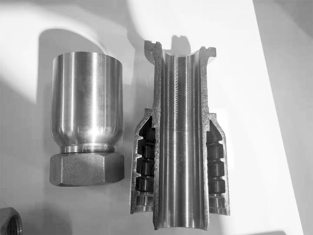
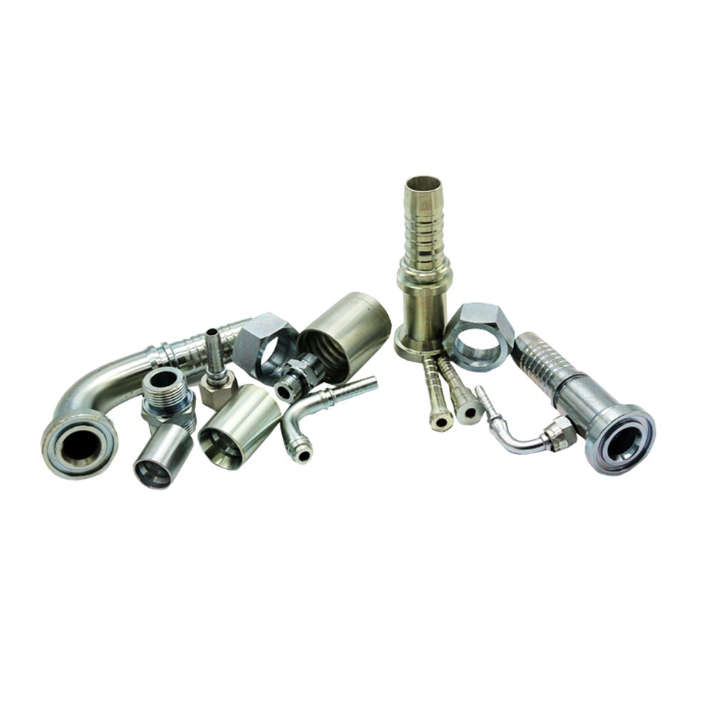
The definition of hydraulic connectors.
The Hydraulic connector is connecting hydraulic pipelines and hydraulic pipelines, or pipelines and hydraulic components (pumps, delivery lines, reversing valves, stop valves, hydraulic motors, hydraulic cylinders, and some auxiliary components; such as level gauges, thermometers), Pressure gauges, etc.). The hydraulic joints include hydraulic joints for hoses and hydraulic connectors for hard pipes. Here, only the hydraulic connectors for hoses are introduced. ), the other end is connected to other components (terminals). In order to ensure compatibility and leak-free sealing with other components, the terminal of the hydraulic hose connector needs to be designed in accordance with the general interface standard. The main function of the end is to ensure that the connector is connected to the hose. The long-lasting seal.
Hydraulic connectors are widely used in hydraulic pipeline systems in various industries such as military industry, power, petrochemical, electric power, ships, cars, rail transit, construction machinery, mining, metallurgy, steel mills, marine engineering, etc.
The raw material of hydraulic connectors
For the selection of material, usually in a non-corrosive environment, both carbon steel and stainless steel hydraulic pipe joints can be used, but in terms of economy, more carbon steel is used, and because the cost of using stainless steel is high. If the environment used is corrosive, only stainless steel hydraulic pipe connectors can be used.
The swaged hose fittings which our company produced are made of 45# steel, the sleeves are all 10# steel, the finish is above Ra3.2, and the size is accurate to 0.02mm. The hose joint nuts are all 45# carbon steel and Q235 Steel.
The thread form conventions of hydraulic connectors are as follows:
Type A is the flathead;
H type is a 26-degree angle inside the flaring;
O type is a flat head that can put an O ring;
Type C is an inner cone with a 60-degree angle. Commonly known as concave. Also called internal flaring;
Type D is the outer ball head. Commonly known as the pointed head.
The form of the slave interface can be divided into the following types:
1)O-ring end face sealing hose connector

1. Hose joint 2. Oil port 3. O-ring 4. Joint 5. Nut 6. O-ring, when the nut 5 is screwed with the external thread of the joint body, as the tightening torque increases, the hose joint Contact with the end surface of the joint body (piece 4) and press tightly, the O-ring on the end surface of the joint 4 is elastically deformed, fully contacts the end surfaces of the piece 6 and the piece 4 and generates pressure to play a sealing role.
Special attention should be paid during installation, and the sealing ring should be checked before installation.
2)24° cone sealing end hose connector

1. Hose joint 2. O-ring 3. Oil port 4. Joint 5. Nut. When nut 5 is screwed with the external thread of the joint body (piece 4), as the tightening torque increases, the hose joint The cone surface is in contact with and pressed against the inner cone surface of the joint body (piece 4), and the O-ring on the outer cone surface of the hose connector 1 is elastically deformed, fully contacting the cone surfaces of the parts 6 and 4, and generates greater pressure, Play a sealing role, due to the leverage of the cone surface, the pressure between the cone surfaces is greater, and the sealing effect is theoretically better.
Special attention should be paid during installation, and the sealing ring should be checked before installation.
3)Flange end hose connector

1. Hose joint 2. Oil port, flange head, flange pressure plate 3. O-ring, the flange head of the hose joint is pressed on the oil port by the flange pressure plate, when the bolt tightening torque increases, the bolt produces a lot The pre-tightening force of the bolt passes through the flange pressure plate to tightly press the flange head against the oil port. The O-ring (piece 3) on the flange head is deformed by compression, and the hose connector (piece 1 ) The end face of the flange head and the oil port face fully contact and produce pressure, which plays a sealing role. Due to the use of high-strength bolts, the pressure between the contact surfaces is very large, and the sealing effect is theoretically very good.
Special attention should be paid during the installation process. Check the end face O-ring before installation.
4)Stud end hose connector

The threaded root of the joint is equipped with an O-shaped washer. When the joint is connected with a port through the thread, the O-ring is attached to the end face of the oil port to play a sealing role.
5)37° Flared end hose connector

1. Hose joint 2. Nut 3. Steel pipe 4. Sleeve, when nut 2 is screwed with the external thread of the joint body (piece 1), as the tightening torque increases, the outer cone of the hose joint and the steel pipe ( Part 3) The inner cone surfaces are in contact and pressed tightly, and the hose connector 1 and 3 cone surfaces are in full contact and produce greater pressure, which plays a sealing role. Due to the leverage of the cone surfaces, the pressure between the cone surfaces is greater.
In the process of selecting hydraulic pipe joints, it is necessary to consider the maximum working pressure of the joint, working temperature, interface size, applicable pipe inner and outer diameter dimensions, whether the installation is convenient, whether it is economical, and other factors. The maximum working pressure of the joint should not be lower than the maximum working pressure of the hose.

In the application scenario, we should notice the below points:
- When replacing or reinstalling the connector, don’t forget to clean the connection end.
- When re-assembling reusable fittings, the O-rings should be replaced in time. O-rings are prone to cracks, which may damage the sealing performance of the system during repeated assembly and result in leakage of high-pressure hose connectors.
There are several reasons for the leakage of high-pressure hose connectors:
1) “о”-the shaped ring is aging or deformed to form leakage;
2) The “о”-shaped ring device is not in place so that when the two planes are connected, the pressure is not flat or the “о”-the shaped ring is cut to form leakage;
3) The “о”-shaped ring is not compacted, and the amount of elastic deformation is lacking and leakage is formed;
4) The “о”-shaped ring spigot groove is too deep to form leakage. In this regard, it is necessary to select the “о” ring with the same outer diameter and thicker section from the beginning or cut or grind the sealing surface with the spigot groove to reduce the depth of the spigot groove to make the “о” The ring has enough elastic deformation (the shrinkage should generally be between 0.35-0.65mm). Regarding leakage at pipe joints using oil-resistant rubber sheet, wool felt, mild steel cardboard, combined sealing gasket or sealant, no matter what the material is, first check whether the seal is damaged, deformed, aging, and excessively rough. , And then adopt the corresponding method. When repairing the leak, the staff disassembled the connectors, threw them on the ground, and reinstalled it. This will bring contaminants into the hydraulic system. This is a bad practice and will shorten the service life of the equipment.
3. Make sure to use the exact same type of connector for replacement, even if it takes longer to obtain such an accessory. Finding a similar connector and trying to make it work (just because it is easy to obtain) is one of the causes of failure. The downtime caused by taking the time to find the right parts is worth it because it can help you save more time and money in the long run.


